
Compare the separate zone valves of S-plan with the shared mid-position valve of Y-plan.
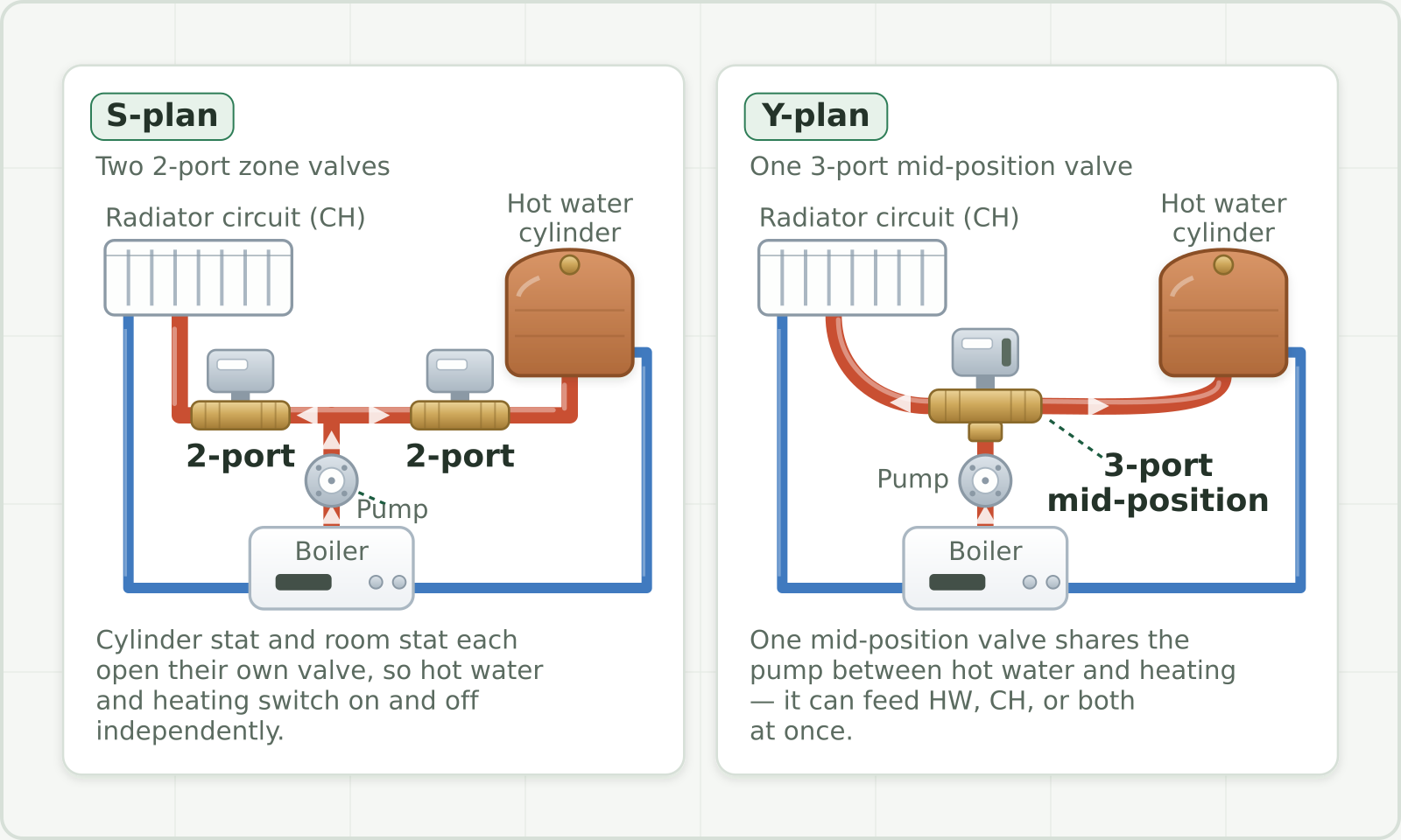
Both layouts heat the same things — a hot water cylinder and a radiator circuit — from one boiler and one pump. The hydraulic diagram compares how the valves route that flow; the electrical demand paths also differ.
On the left, the S-plan uses two separate 2-port zone valves: one valve feeds the cylinder and the other feeds the radiators. Each valve is driven independently, so the cylinder thermostat and the room thermostat can call for heat on their own.
On the right, the Y-plan uses a single 3-port mid-position valve. It shares the pump between the two circuits and can send heat to hot water, to heating, or to both at once.
How the valves actually fire the boiler
In a conventional S-plan, a thermostat demand opens its two-port valve and the valve’s auxiliary contact supplies the boiler demand. In a conventional Y-plan, the cylinder thermostat can supply the boiler demand during hot-water operation; the mid-position valve’s internal switching provides the heating-only path. A Y-plan valve does not close both outlets when demand ends.
Interlock removes the normal firing demand when the heating and hot-water controls are satisfied. It does not require every valve to be shut or every electrical supply to be cut. Preserve the boiler’s specified pump overrun and protective functions, and follow its wiring diagram with the chosen controls.
Telling them apart on a fault
An S-plan valve that fails to open can leave its own zone cold while another still heats. A valve stuck open or an auxiliary contact stuck closed gives a different symptom, so identify the failure mode before condemning a part. On Y-plan, check the shared valve’s movement and electrical demands for hot water only, heating only and both together. A symptom narrows the checks; it does not prove which component failed.
Use the schematic to lock in the difference: S-plan means two valves working separately; Y-plan means one valve sharing the flow.
Something wrong, unclear or out of date? Report an issue with this note.